Here you will find PCBs I have designed using Eagle or KiKad.
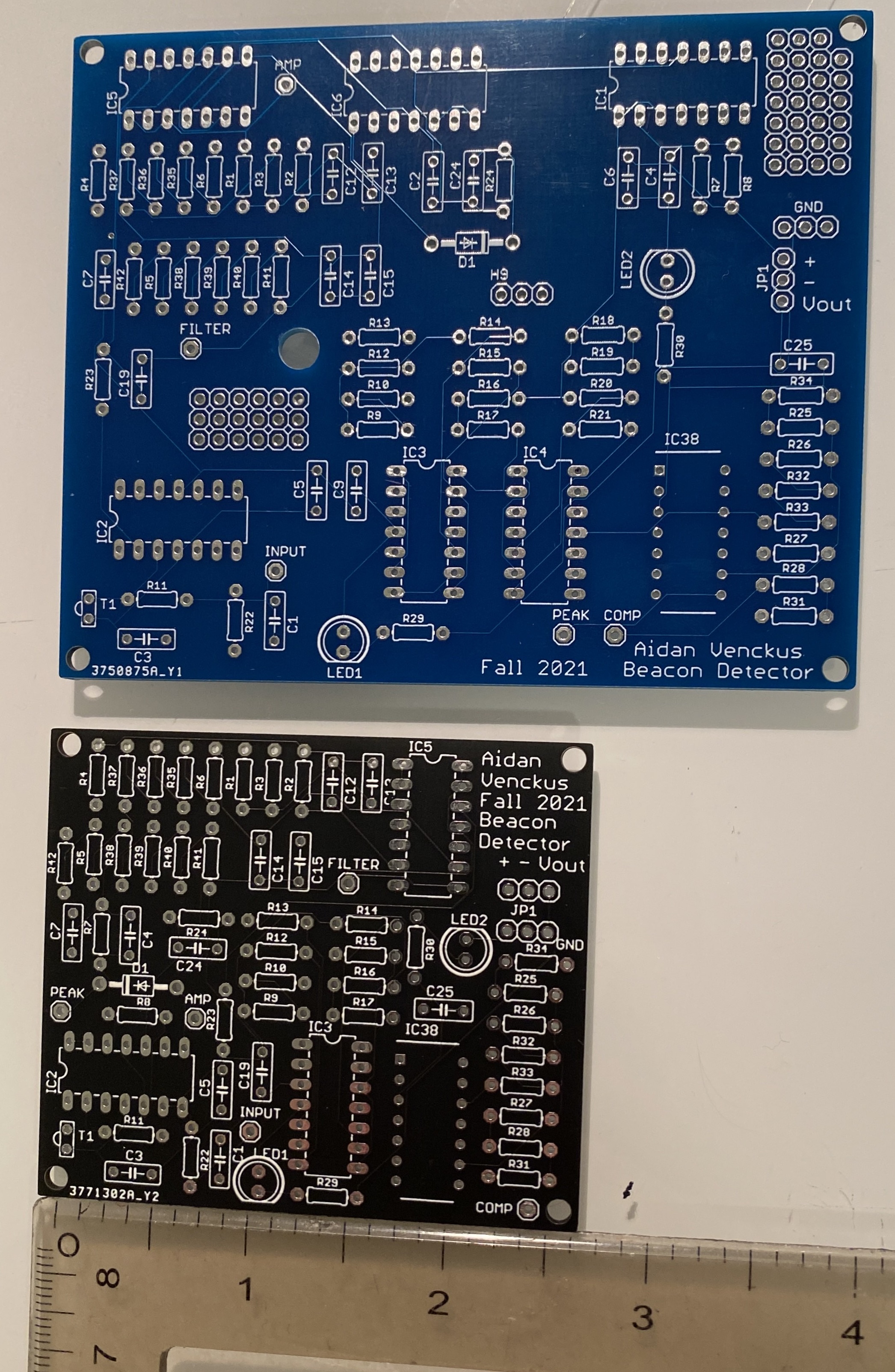
Beacon Detector v2:

I needed to revise my previous Beacon Detector because I had made a few mistakes that were worth designing a new PCB for. I had made my traces too small which led to some of the ones that I used to have traces scratched which acts like a cut wire (I changed this after ordering). In addition my previous design had a couple op amps in positive feeback accidently in addition to having additional unnessesary gain stages (from 6 to 4). Lastly I did a complete size reduction and compacted all the components by moving them and utilizing all the op amp ports.
Beacon Detector v1:
This was a breadboard and perfboard circuit that I had to design as part of my capstone to be able to detect IR light from a distance away, I decided that it would be good practice and fun to try to design it into a pcb board using eagle.
Trackwire PCB:


This was a trackwire detector which I used on my capstone autonomous ground robot. It worked based on a inductor that would try to read the magnetic field of a wire with osilating current running through it, take the signal, amplify it, then sample the signal through a peak detector and comparator. This allowed the signal to go from analog to a digital high and low to be read through an LED and in most cases the microcontroller IO.
Ornament PCB:


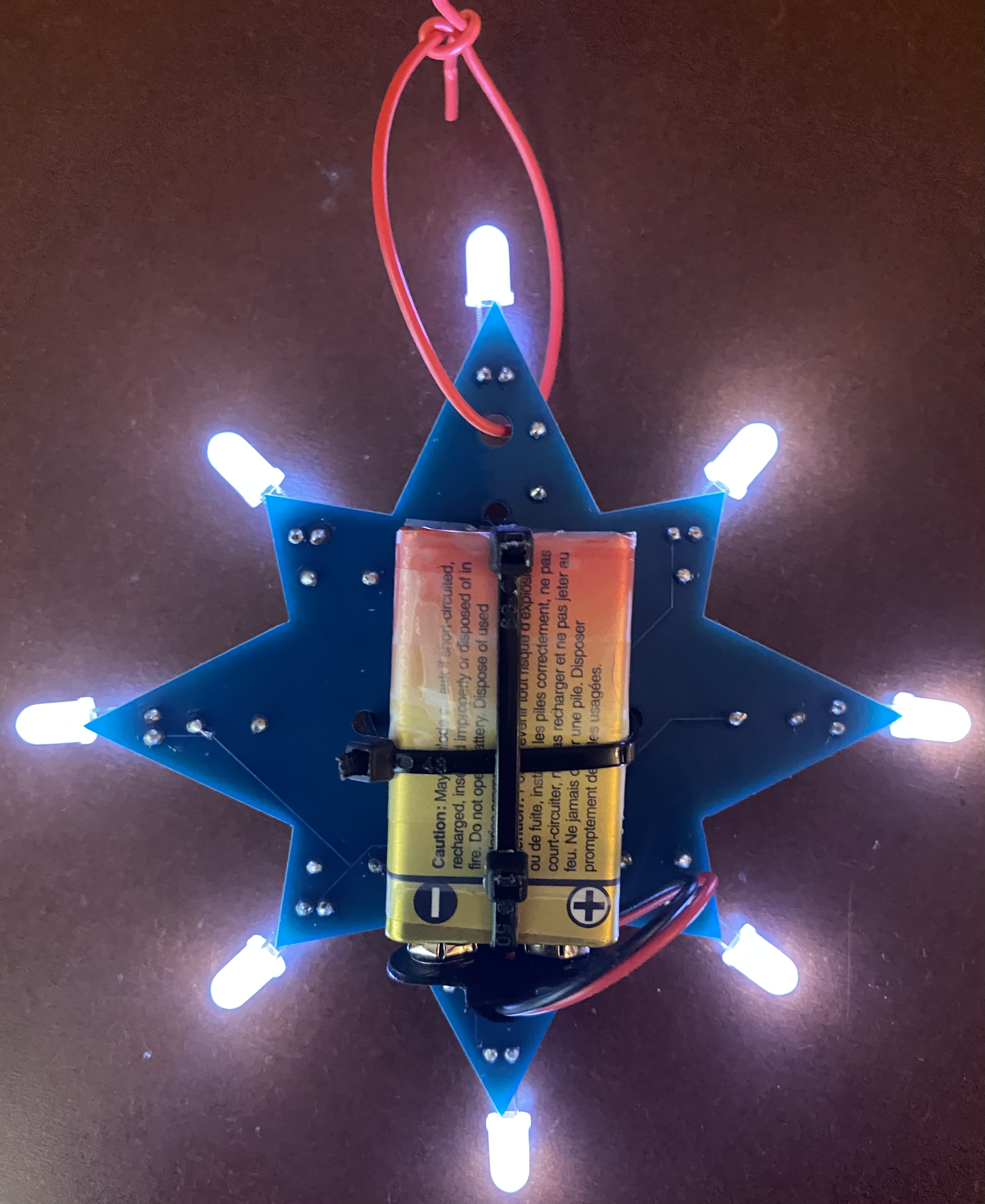
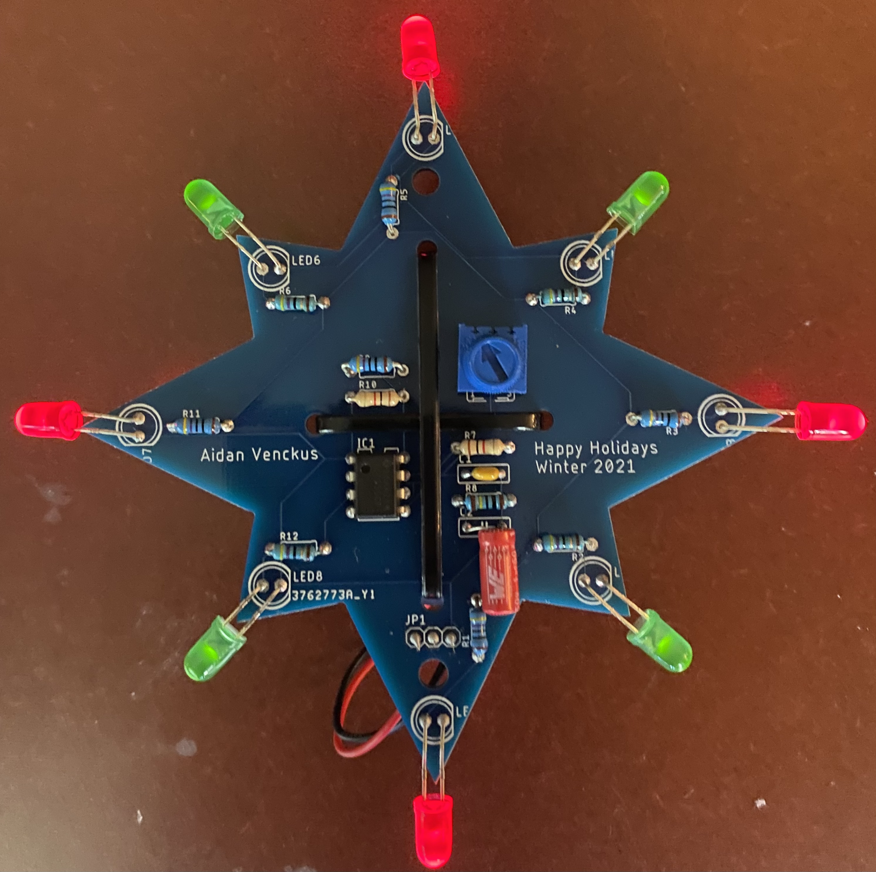
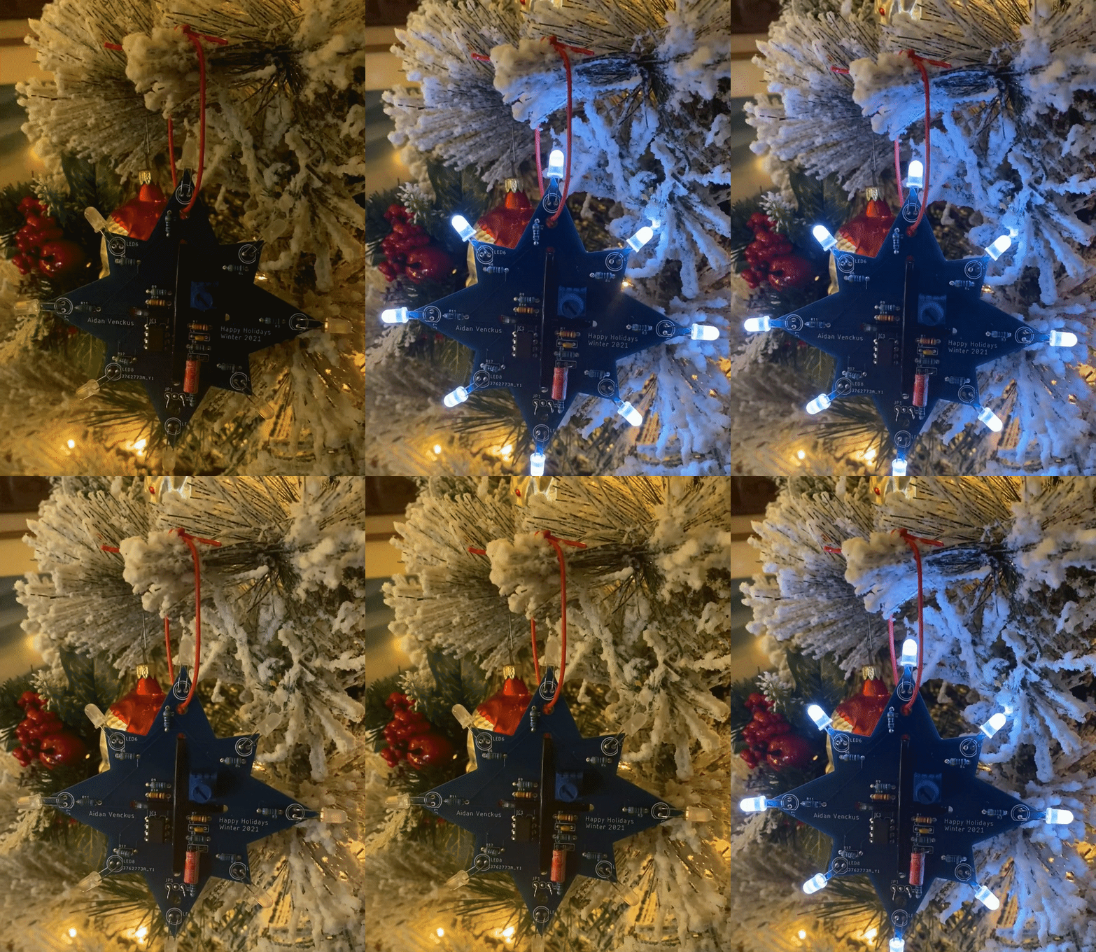
This year for the holidays I gave a few Ornament PCBs to my family and friends. The PCB ran on a 9V battery and would flash its LEDs based on the resistance of the potentiometer on it connected to the 555 timer. This allowed for the speed of the flashing to be configurable and custom. In addition to this you are able to change out the LEDs for other colors but the resistors would need to be changed as different colored LEDs require different voltages to run. I changed the schematic after ordering the PCB as I started to increase the size of my traces on the PCB in addition to the size of the power and ground traces to be larger.