Here you will find Active and Past projects I've either made for school or in my freetime
The code of the projects that I've done at UC Santa Cruz are mostly redacted in order to maintain academic integrity.
Mechatronics Capstone Project:

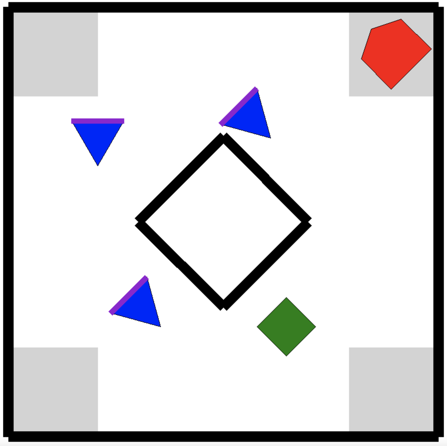
Introduction: The purpose of this project is to design, build, and program an autonomous robot that can complete a randomly generated field. The completion of a given field consists of detecting triangular vats scattered around that can be detected by infrared beacons on top of them. In order to complete a vat, the bot needs to deposit a ping pong ball into the correct hole. The proper hole is designated by a strip of black tape beneath the hole in addition to the correct side which is designated by a trackwire on the perimeter of the correct face.
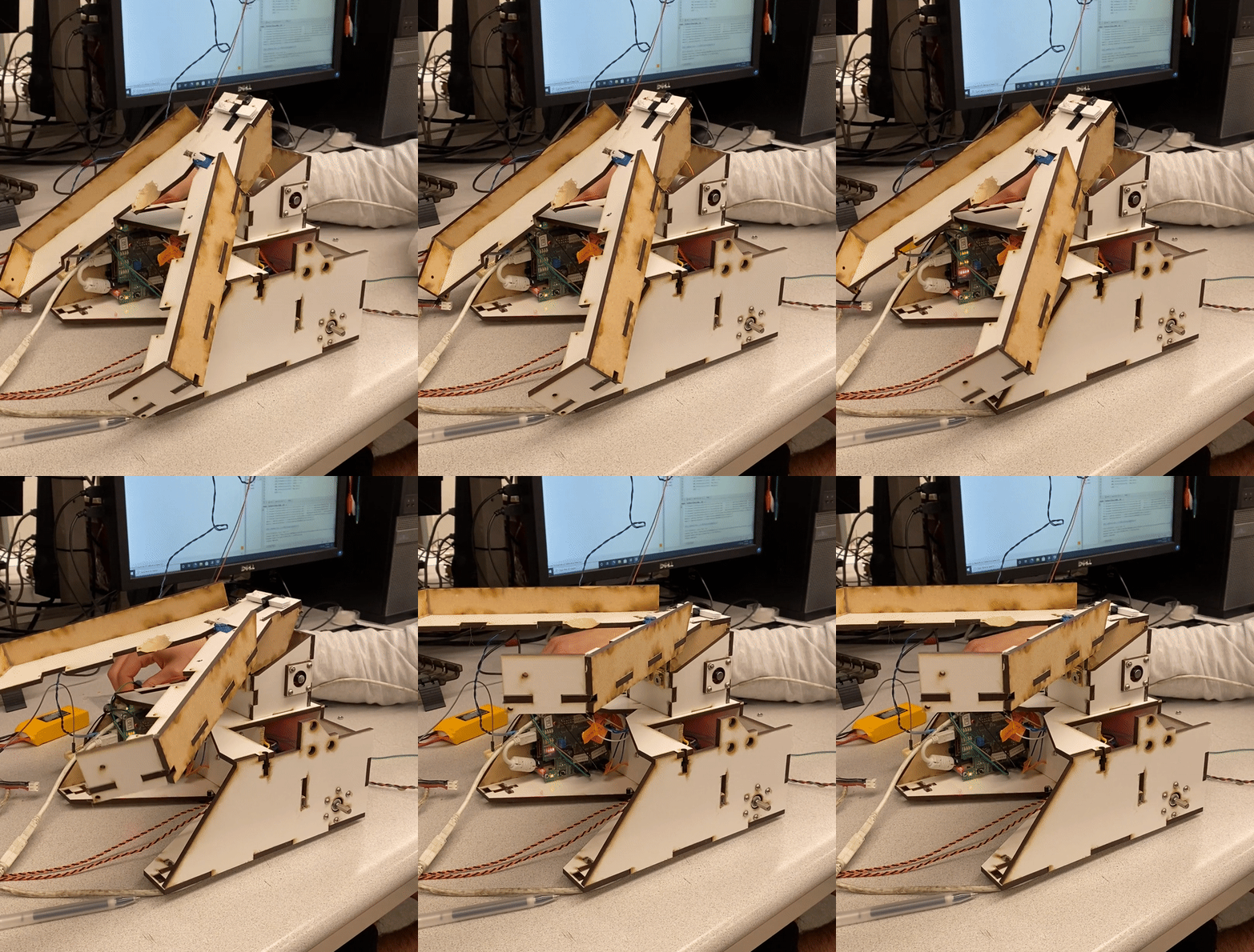
Idea: To build the bot I needed to utilize a combination of computer science, mechanical engineering, and eletrical engineering. To start I first needed to design the bot based on the challenge and keep it as simple as possible. Our first goal was to make a draft that would be ready for the peer design review (PDR). The approach taken was to construct a robot that could access two sides of the vat towers at a time, using a V-shaped cavity in the center to attach to a corner, allowing a ping pong ball to be deposited to any of the holes on either of these sides. Noting the vat tower faces are ten inches wide, this strategy requires a large robot. Given the restriction of having a maximum dimension in any direction of eleven inches, to account for the size, we set off to create a robot that could fold in order to meet the specifications.
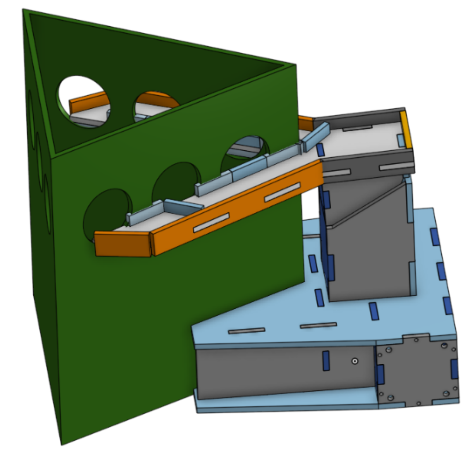

Approach: The strategy consists of attaching to one corner of the tower and using two track wire sensors to quickly identify if the correct face of the tower is accessible from the currently attached corner. If the correct face is found, the upper deposit arms, consisting of servos and tape sensors to control gates on the arms depending on the location of the black tape on the vat tower and the correct face location, act as a gravity feeder. In the case the robot attaches to a corner where the correct face is inaccessible, an algorithm is implemented to attempt to attach the bot to a new corner of the vat tower. We aim to use bumpers on the deposit arms for obstacle detection and to help aid the corner mating procedure. With this approach, the robot is capable of completing any tower after attempting a maximum of two different corner locations. This approach was chosen due to the design easing the need for a precision ball release method as well as the speed improvement gained by the simpler method of identifying proper alignment with the tower.


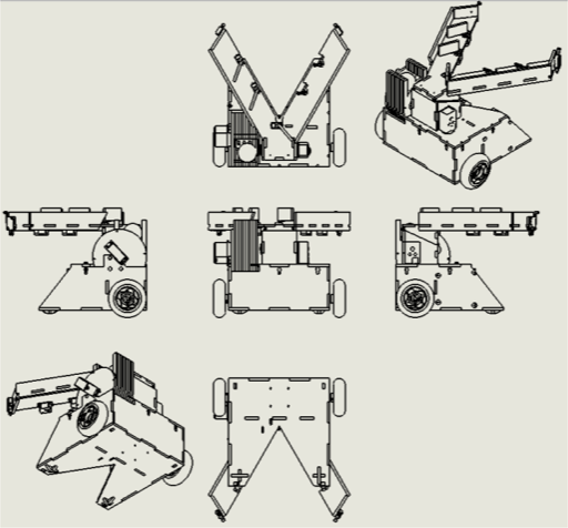
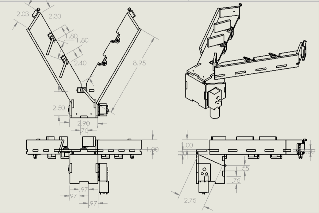
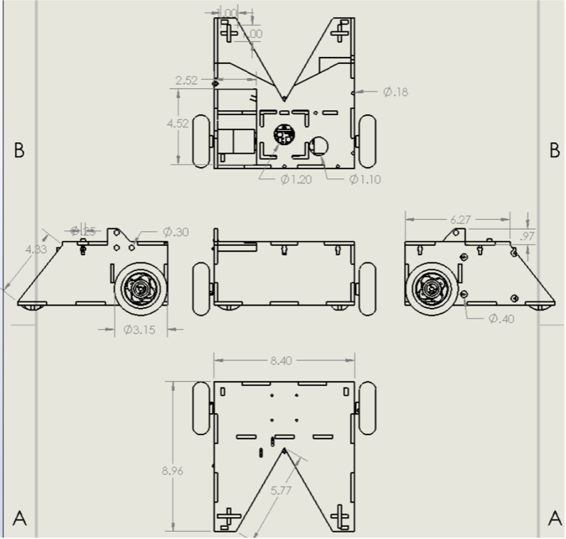
Mechanical design: A unique aspect of this course is using SolidWorks to create designs that are then cut using a laser cutter for quick and accurate manufacturing and prototyping. The process starts out with an idea, which we then CAD each individual object called a part using SolidWorks. As soon as a working model is made, each part is then taken into an assembly where it is then “mated” together to see if it will all fit together and no collisions exist. By creating this solid model, we can confirm and identify shortcomings before attempting any physical prototyping. To get the parts prepared for laser cutting, each part is taken into an assembly where it is mated onto a bottom face so all the parts are lying horizontally. It then gets converted from an assembly to a drawing where the horizontally laid parts become drawings on a sheet. It then needs to be scaled to a 1:1 ratio where it can then be exported as a DXF (autoCAD Drawing interchange) file to be cut on the laser cutter.
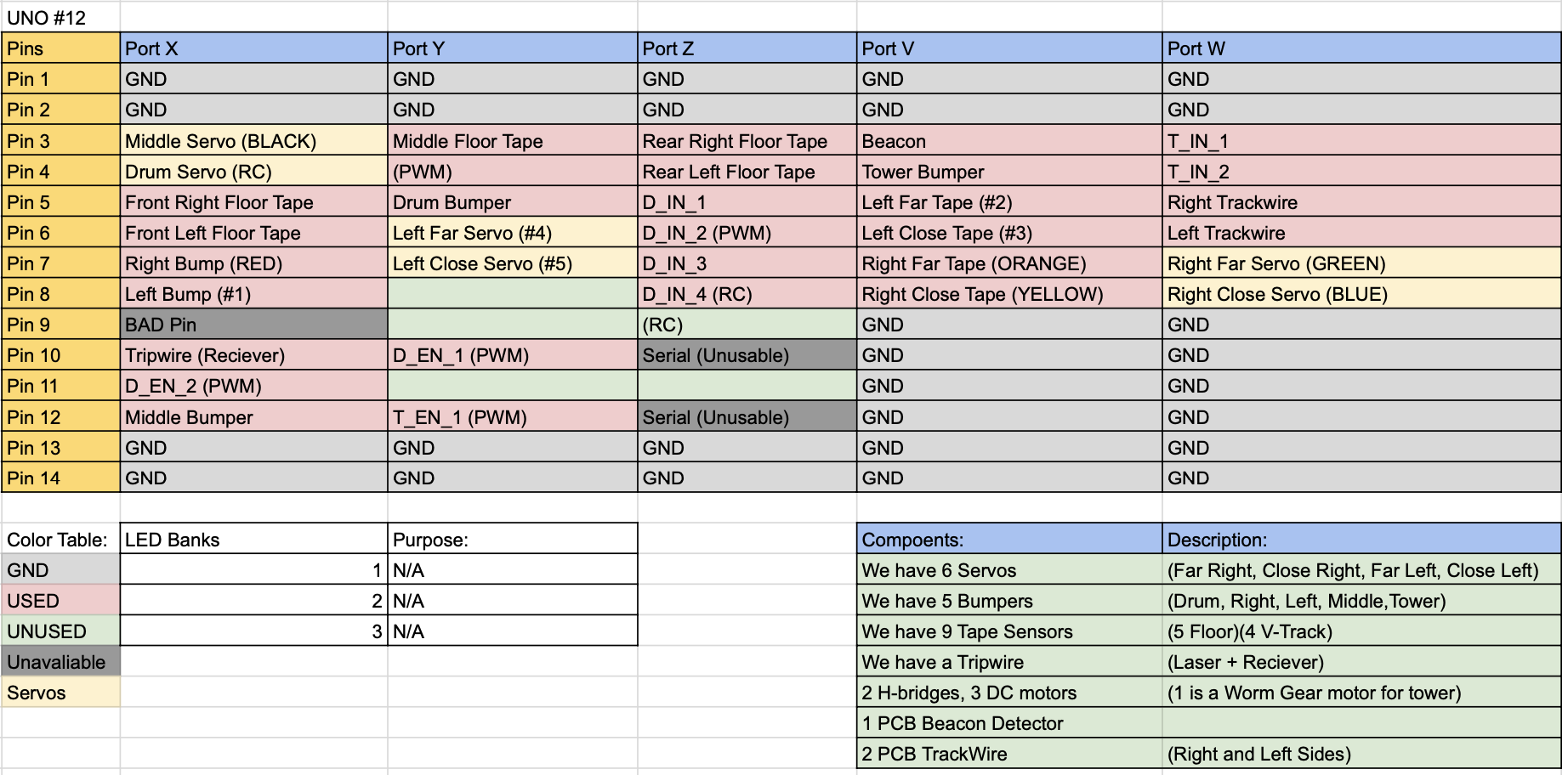
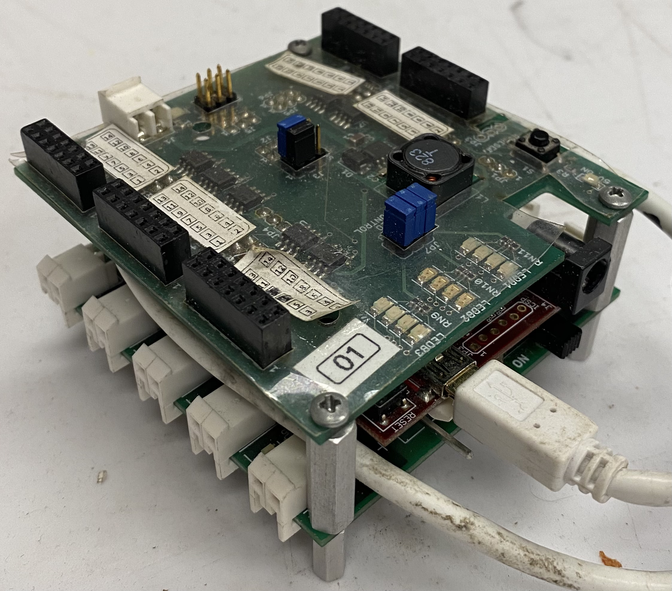
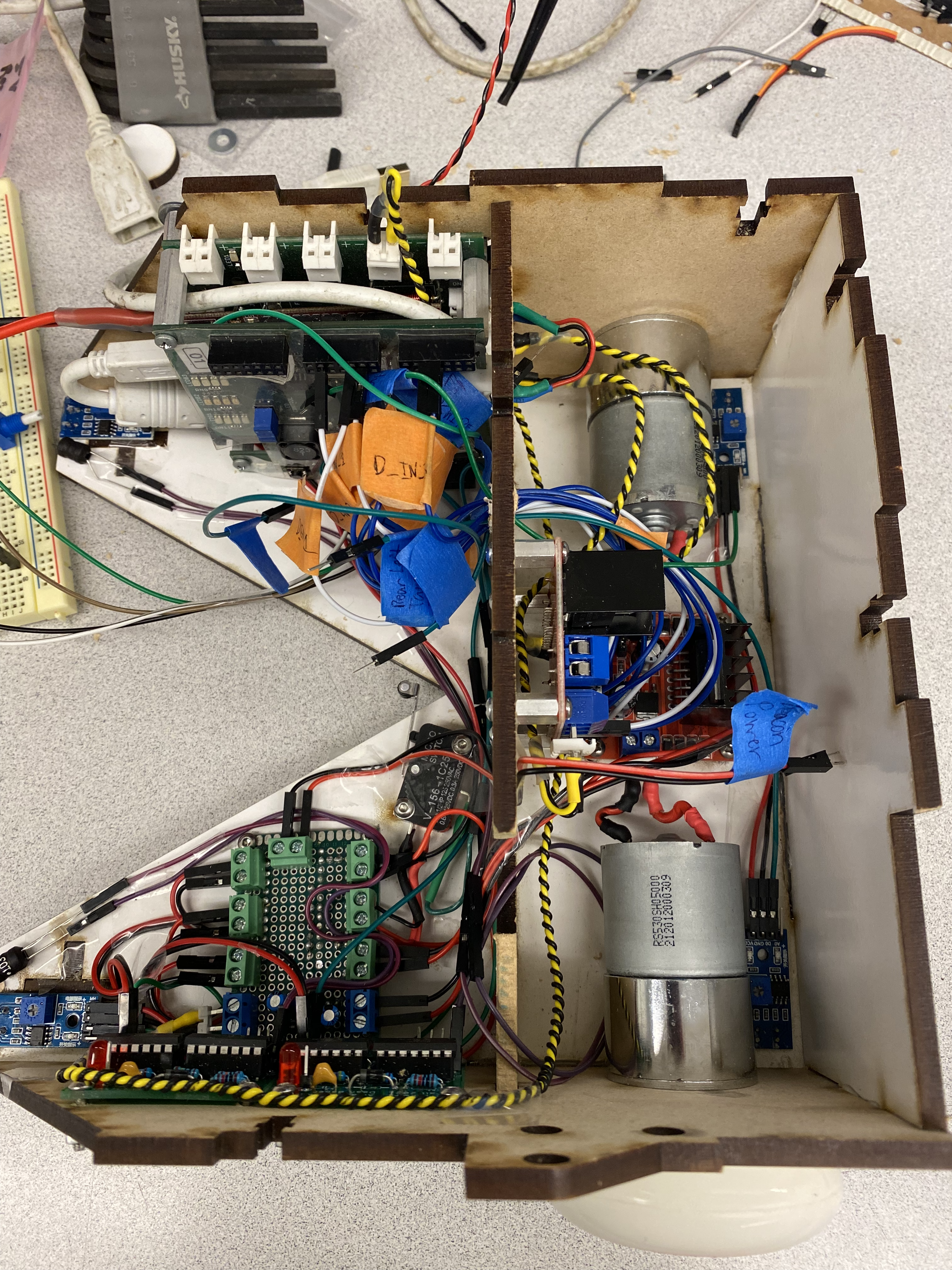
Electrical design: The main portions of the electrical work for the bot came from doing the beacon detector and trackwire detector which was done through the use of PCBs. The beacon detector is responsible for finding the ring of IR LEDs that lay on top of the vat tower. The goal of the beacon detector is to accept and identify a 2 [KHz] signal while rejecting 1.5 and 2.5 [KHz] signals. For the circuit we had the input go into 4 gain stages of non-inverting op amps, then through a bandpass filter that attenuates the signal, through a peak detector, and lastly to a comparator to make it a digital output (PCB info).
The trackwire circuit is responsible for detecting the trackwire through the vat tower which is a 12V wire with oscillating 25kHz current running through it causing an oscillating magnetic field. The circuit utilizes a tank circuit which acts as a resonant oscillator and gets the signal from the trackwire's magnetic field through it’s inductor. The capacitor fills up with charge and it oscillates because the capacitor gives charge to the inductor and then the capacitor flips polarity (this causes a sine wave). It is described as a tank because the oscillation can be imagined as a tank with water in it swishing back and forth. From there it consists of three gain stages of non-inverting op amps. It then goes to a peak detector to provide rectification of the inputted AC signal. The output is then buffered with an LED at the end (the voltage difference turns the LED off when a trackwire is detected) (PCB info).
Other electronic components include working with various motors and acutators such as servos (fixed and continour), DC motors (geared and worm geared), H-bridges. In addtion to this we had various sensors such as tape sensors reading both digital and analog signals, tripwire (laser) triggers, switches acting as bump sensors, and many 5V and 3V regulators to drop us down from the 9.9V battery power supply.
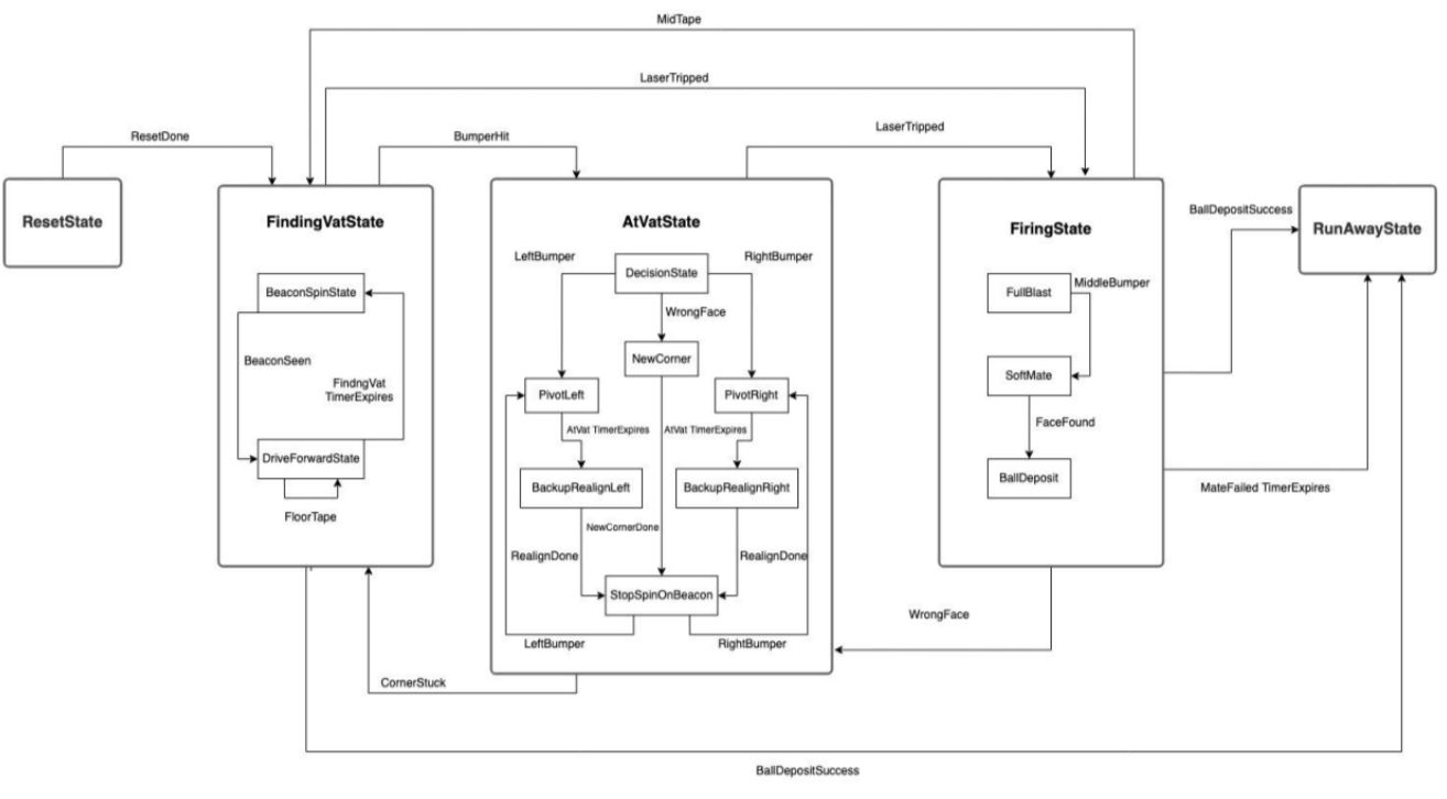
Software design: The code for the bot utilizes a hierarchical state machine design which acts as a standard Finite state machine but each state can have their own “sub” state machines within them. The way that this works is an event is passed to the lowest level it can go and if the state is handled the sub state machine “consumes” the event and returns ES_NO_EVENT to the top level state machine.
The top level states used consisted of a ResetState, a FindingVatState, a AtVatState, a FiringState, and a RunAwayState.
The ResetState deals with the initialization of the bot. This includes raising or lowering the vtrack and resetting the ball drum to allow it to be filled with new ping pong balls.
The FindingVatState deals with finding the vats and driving towards them while dealing with tape events. It transitions into AtVatState when a bumper is hit. This state handles the case when spinning and no beacons are found after an extended period of time.
The AtVatState deals with maneuvering around the vat tower and attempts to cause a laser event. This state ignores tape events when realigning with the vat tower after failing with a pivot only. This can be optimized to react to tape events to stay within the boundaries, however, given that the fields are generated in a way that the correct face must be reachable, we found it was mostly unnecessary for completing the task. This state also handles the maneuvering when mated with the wrong face of the tower and the case when the bot is incapable of maneuvering to the next face.
The FiringState deals with attempting the full mate with the tower after the laser is tripped. Once fully mated, the state deals with readjusting to ensure the bot is flat and checks if at the correct face. This was necessary as using the method of going full speed to slide into the corner often resulted with the bot being positioned propped up against the corner. As our firing method relies on a gravity deposit, this had to be corrected by backing up and coming in at a slower speed. This state also handles checking for the trackwire, and, if at the correct face, the state handles depositing the ball into the correct hole by moving the appropriate servos. The servos that are moved are the ball drum servo, the middle servo determining the side the ball would roll down, and the arm servos if tape was found on inner two holes of the tower.
The RunAwayState deals with getting the bot in a position in which it could likely find a new vat tower. This state is entered either following depositing a ping pong ball or in the case that both attempts to reach a new corner of the vat fails. It is used to get out of situations in which the bot can not make progress. The sequence is simple, starting with backing up from the tower and then turning partially while ignoring beacons. It then transitions into the FindingVatState and continues its spin now looking for beacons. This state could be converted into a tape follow state that would search for corners of the field to give better chances at finding all the towers. This was implemented though we decided that the basic method of spinning was quick and was efficient at getting the two towers needed.
Our design implemented three substate machines. FindingVat, AtVat, and Firing are implemented as substate machines.
Mechatronics Lab3:

In this lab I got the chance to test various motors to be used in the capstone project. I got the chance to use servos, stepper motors, and DC motors. We had a power distribution board that was able to power the motors with 5V and 12V when necessary and was able to use H-bridges and various dedicated boards to run the motors. In addition we had to solve some inductive kickback when working with the DC motors and worked on different type of step methods for the stepper motor. I had the chance to try wave step, full step, and half step. The type of step that is most often used is micro step with sin wave phasing but I didn't have a chace to try it.
Mechatronics Lab2:


This is the Bot I created by using solidworks to design the individual parts, assembled them together and made sure all the parts fit together. I then put all the parts on one plane and created a cutout design to then send to the laser cutter.
Mechatronics Lab1:
This was the final product of creating the Beacon circuit that could detect an IR LED from over 20 feet away.
Mechatronics Lab0:
This was part 7 of the Mechatronics Lab0, used the stick to the right wall maze rule to get to the end... Too sleepy to put more description right now.
This was part 8 of the Mechatronics Lab0, we needed to implement a hierarchical state machine instead of a finite state machine... It also has a little dance which I accidently coded to be 2x as long as it was supposed to be. Too sleepy to put more description right now.
CITRIS: Drone Training:
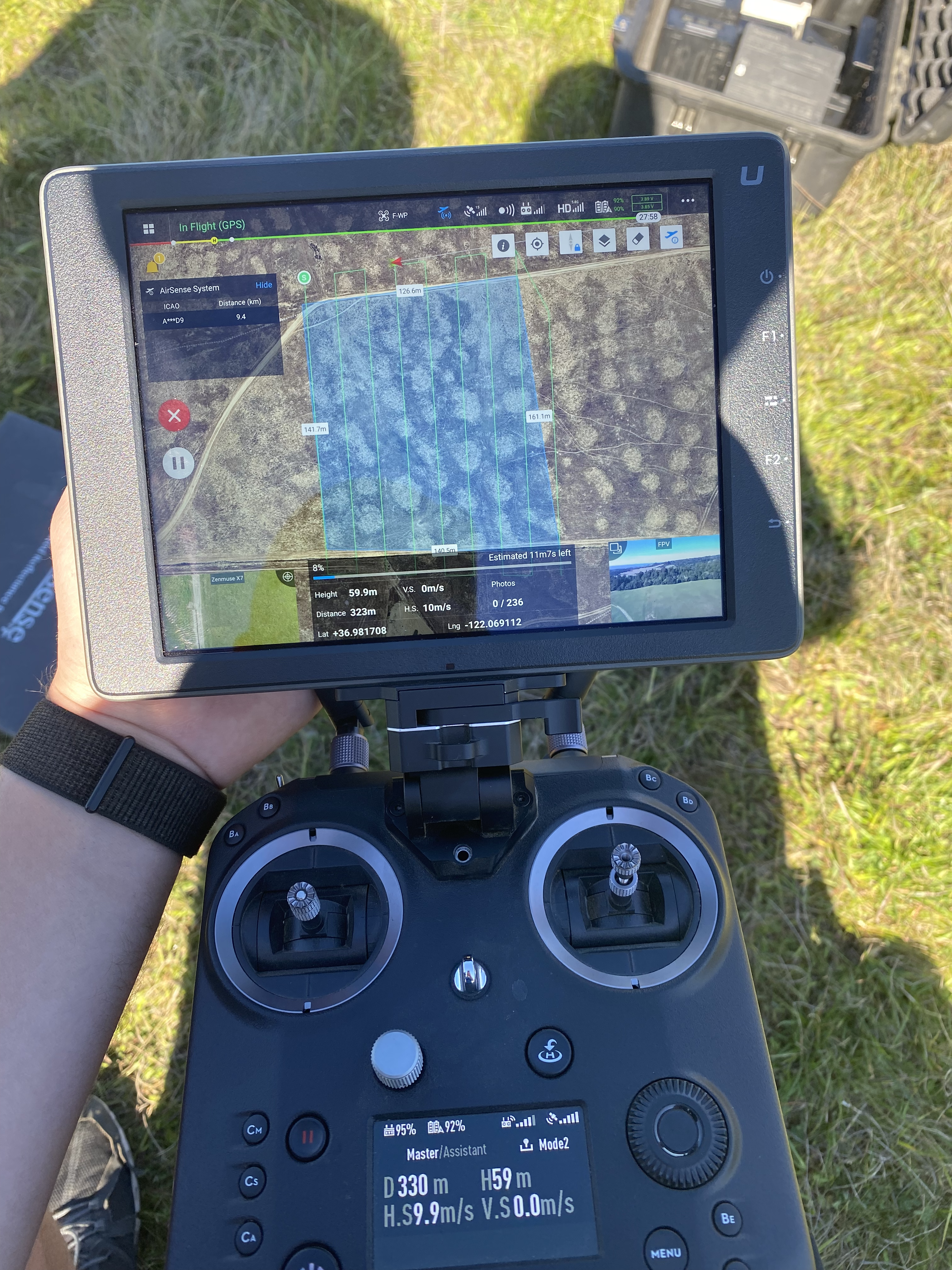
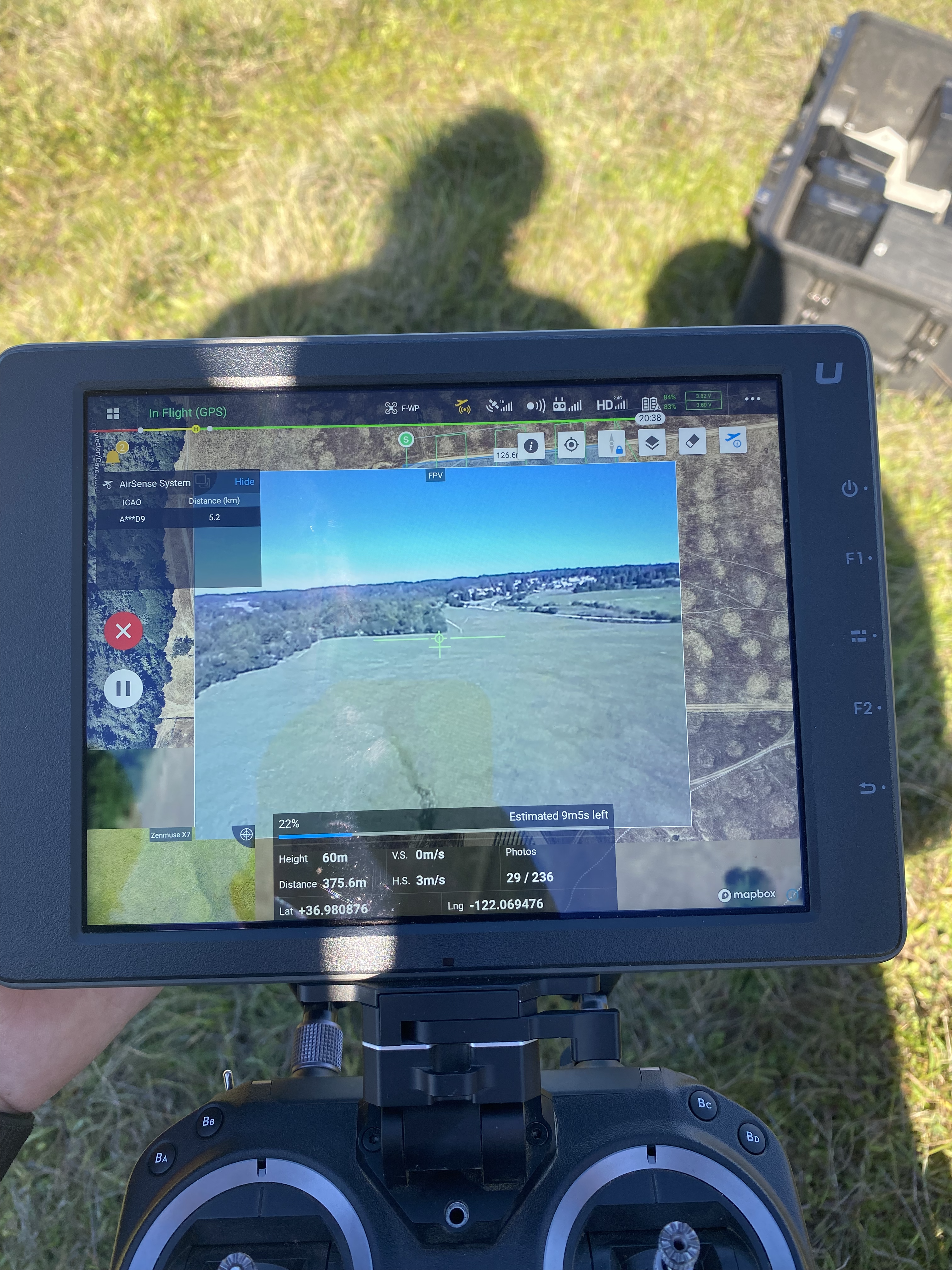
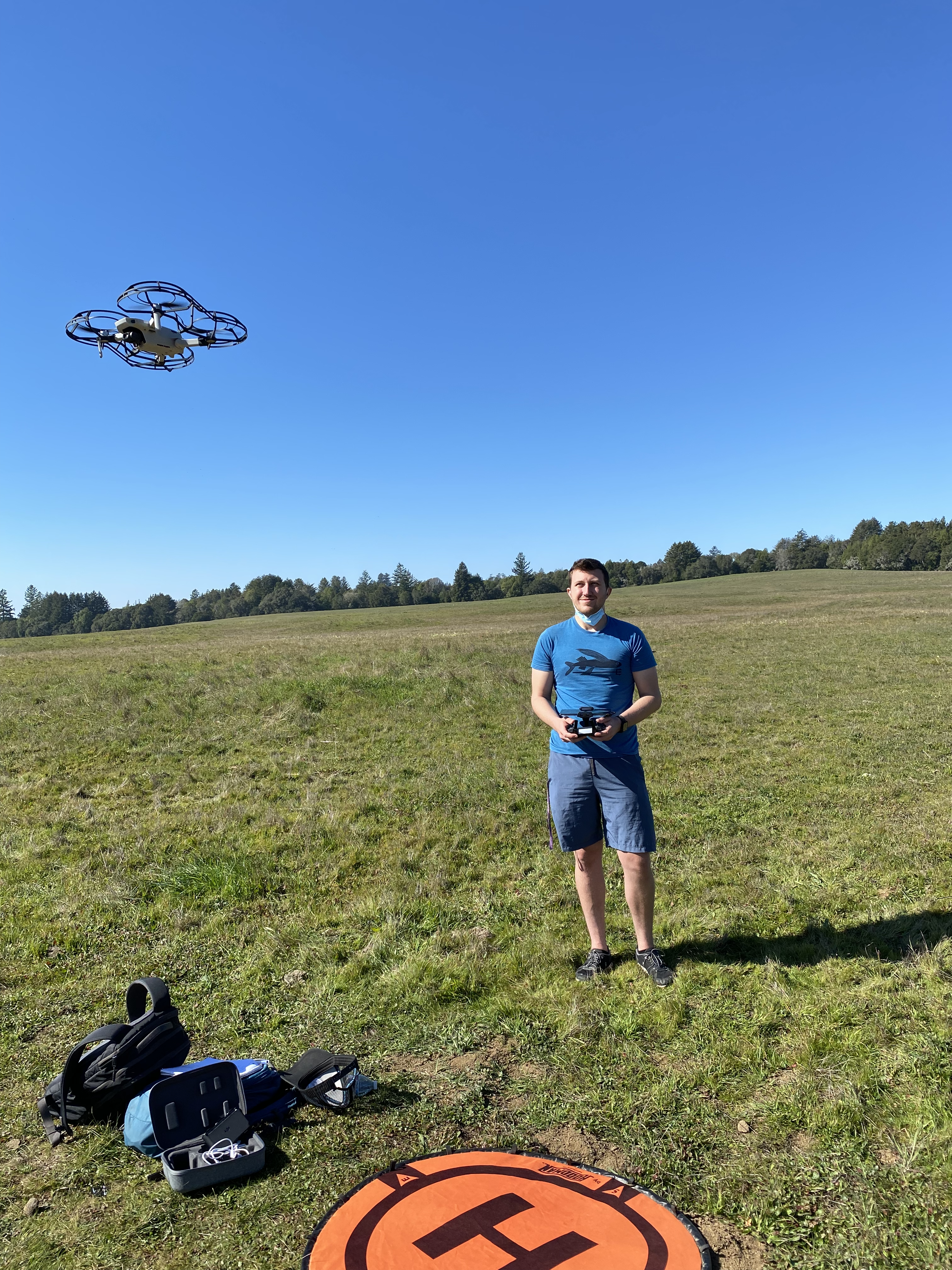
In the Winter quarter of 2022 I was able to take part in a drone training program that was partnered with UCSC and funded by the CITRIS and the Banatao Institute to teach students how to fly various drones, take data, plan autonomous missions, and earn their part 107 Remote pilot's license.
Below I have images of one of the many flights we did which allowed us to collect photogrammerty data in a app called Drone Deploy. This program allows you to plan flights on a google earth view and upload those flights directly to the compatible drone to fly, take images at a certian altitude (for even cm/px resolution), and stick the images together for a final result. The flight is completely autonomous and will takeoff and land for you.

Designing Flight - UAV from Scratch:
UAV V3 (3D Printed)
In this new version of the UAV I tried to design it from scratch and manafacture it by using 3D printing.
For the 3D print... (In progress)


UAV V2
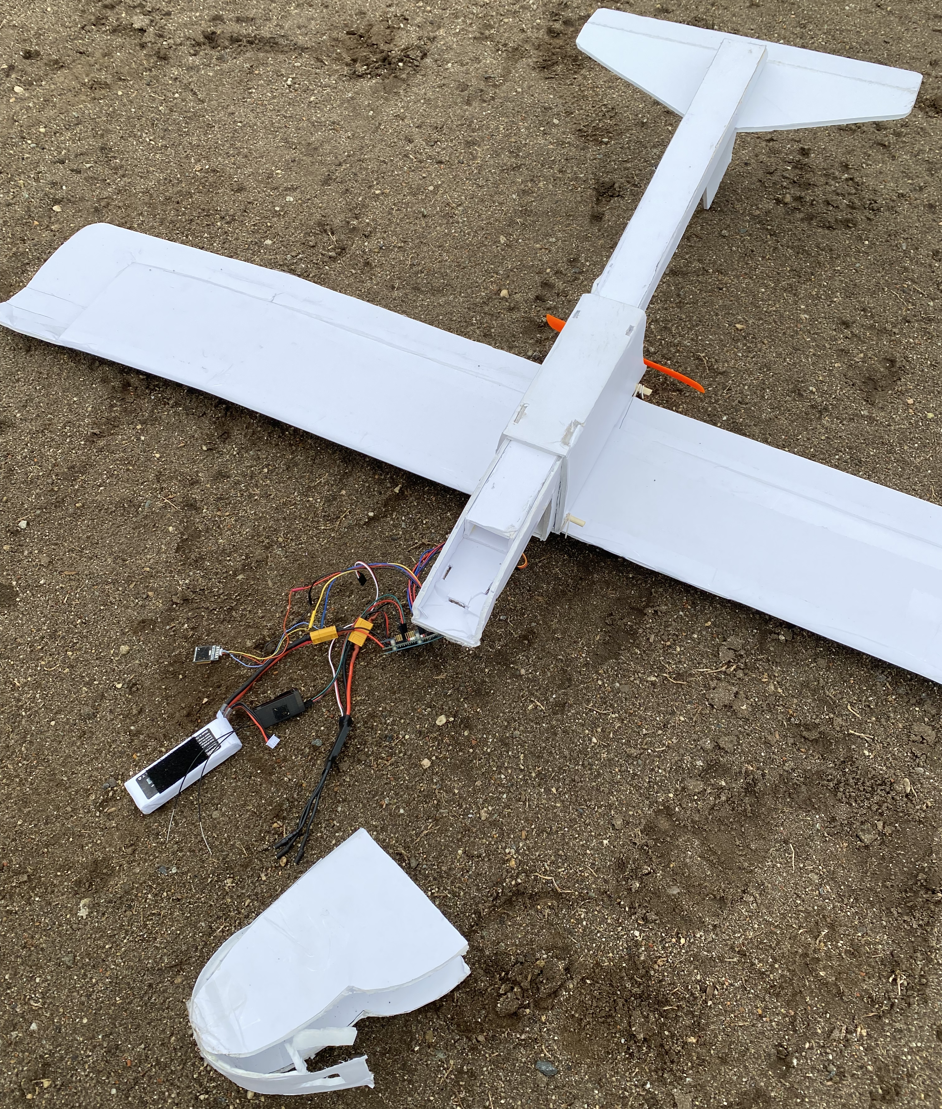
In this new version of the drone I fixed many of the issues that I found while flight testing V1.
- The foam that I used for the wings is a lighter and cheaper dollar tree foam rather than the elmers branded foam board. Although this took some of the structure from the plane, I made up for it by keeping fuselage out of the stronger foam and reinforced it with wooden dowel rods on each corner to prevent bending. This allowed for the plane's foam to compress on impact, but not bend or break if any rough landings happen.
- Adding dihedral to the wings allowed the plane to self level even without any controls. Dihedral is defined as wings that tild upward, which increases lateral stability in a bank by causing the lower wing to fly at a higher angle of attack than the higher wing. This causes more lift to be given to the lower wing causing it to recover. The only downside to dihedral that should be noted is that the wings no longer cause purely vertical lift which can lead to drag and decreased roll rate, but this is all worth the stabillity it allows.
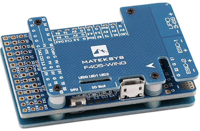
- I got the flight computer running ardupilot firmware to be able to do stabilization so the Yaw, Pitch, and Roll get corrected automatically allowing for a hands off flight. This has lead to there being no crashes so far in the current version and full flights even in winds 5-10kt. vb
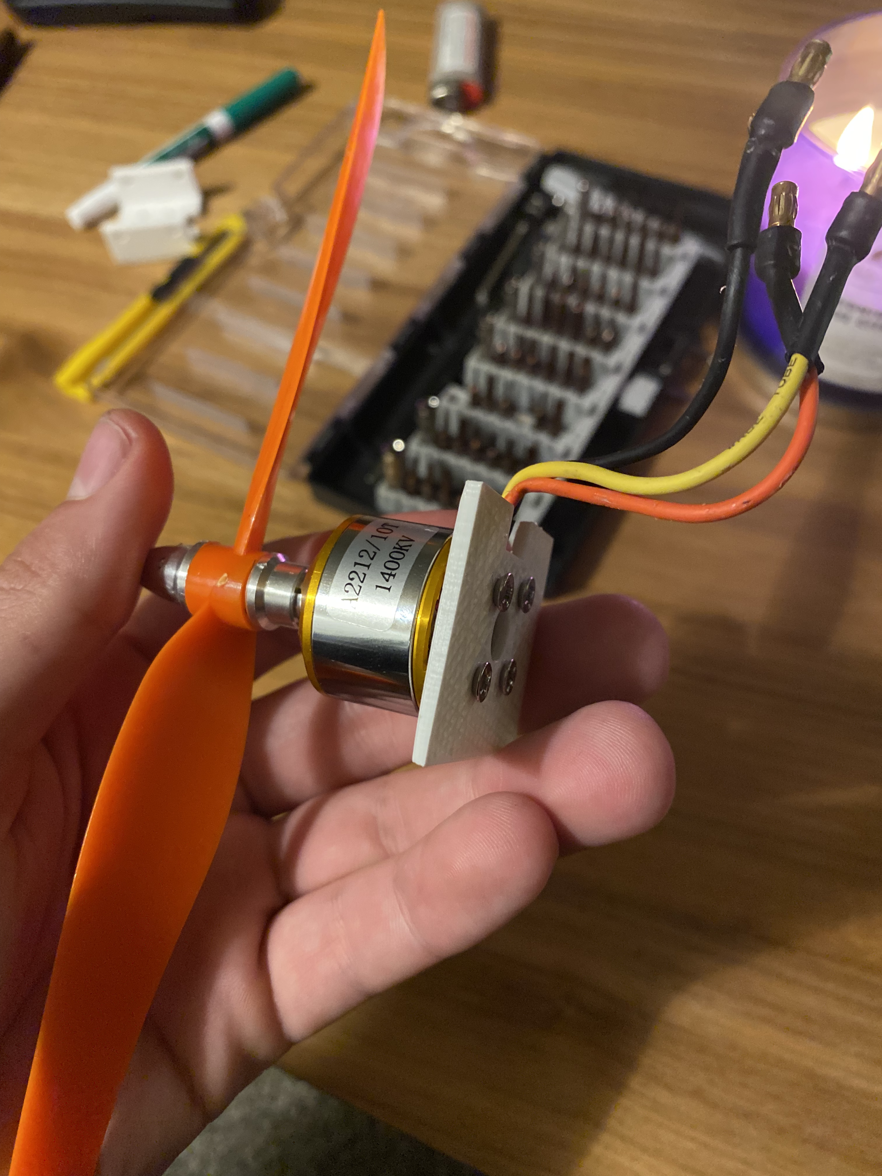
- I reduced the weight by stripping any unnessesary parts from the fuselage and moved the motor to the front.
- A huge focus went to making sure the center of gravity (CG) was in the correct spot instead of an estimate. The CG is defined as lining up with the center of lift of the plane which is on average 25-33% on the front of the wing. This can change from aircraft to aircraft because they can vary in weights and shapes.

UAV V1
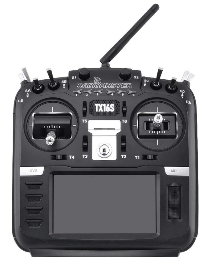
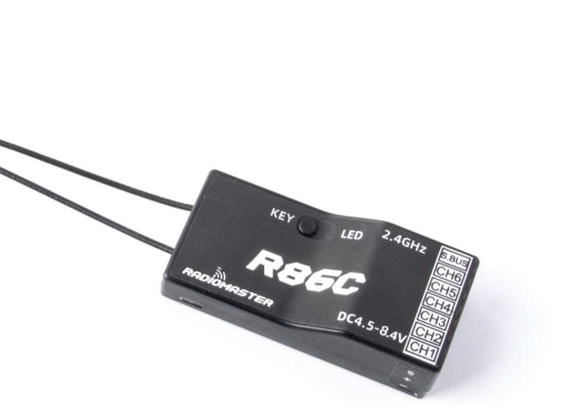
In this project I designed and built a UAV as a start to my goal of creating a long distance autonomous drone that can be retrofitted for various tasks. I started this project by deciding on what type of drone I wanted to build, my favorite of which are fixed wing aircraft that have a glider type of airframe because they are more fun to fly. I decided on doing a 4ft wingspan fixed wing single motor design that would have the motor mounted on top of it to allow for gentler crashes and easier training. The firmware of the flight controller is ardupilot with mission planner installed to utilize the sensors and data avaliable.

"TinyScope" Osilliscope:

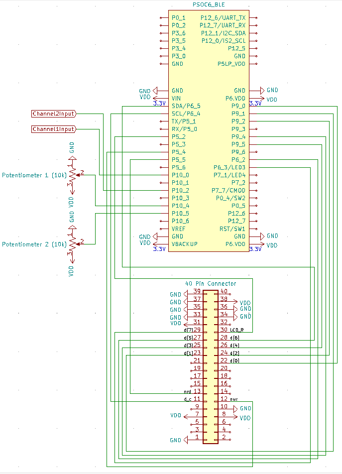
The "Tinyscope" dual-channel oscilloscope that I designed for my Embedded System Design class at UCSC.
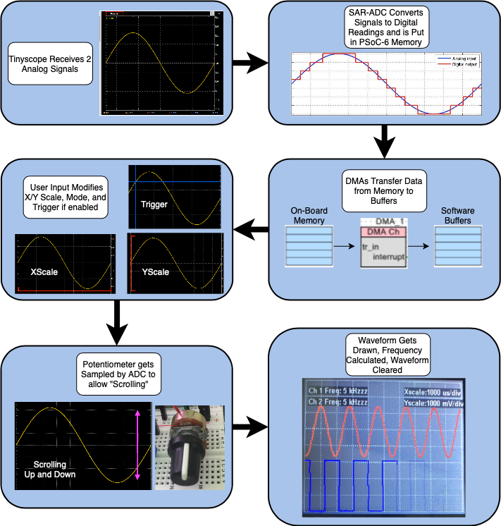
The Tinyscope is made from a PSoC-6 microcontroller programmed and compiled in the PSoC Creator (ver 4.4) that holds similar features as a standard osilliscope would.
An oscilloscope is a type of electronic test equipment that allows the user to probe analog signals and plot them as digital signals in units of voltages over time.
Oscilloscopes are useful as they assist in finding the amplitude, frequency, distortion, and other characteristics of signals.
The Tinyscope allows all this information to be found for a limited range of voltages at a fraction of the size and cost of a standard oscilloscope.
